
The third parameter ("TF" in the example) is the SIMO linear system to apply the simulation too.

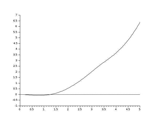
a vector giving the values of u corresponding to each t value.a list : list(ut,parameter1.,parametern) such that: inputs=ut(t,parameter1.,parametern) (ut is a function).The first parameter in the csim function is the simulation function to apply to the transfer function. 'csim' performs a general purpose continuous simulation function and can be used in various ways. Xgrid(1, 1, 10) // Define a nice grid for the plot to make it easier to read Xlabel("Time ") // Add a title and label axis Plot2d(t, csim('step',t,TF)) // csim applies the step test and plot2d produces the graphical output T=0:0.01:3 // Define a time range for the step test
#Csim scilab code#
Which is produced using the following Scilab code If we subject the example transfer function to a unit step test we get: Step responses are a standard way to represent a dynamic system and to visualize the function. Clean removes rounding errors and is recommended. TFx = clean(ss2tf(SS)) // SS -> TF conversion. Scilab has a functions to perform the necessary conversions.Ĭonversion to state space is achieved via:Īnd to convert back to transfer functions you can use: This transfer function will be used in subsequent demonstrations on this page.Ĭonverting Transfer Functions to/from State Space TF = syslin("c", (5*s + 10) / (s^2 +4*s +5)) // Define the linear continuous transfer function

S = poly(0,'s') // Define the complex number frequency parameter. This is created in the Scilab console by the following: 1.2 Converting Transfer Functions to/from State SpaceĬlassical Control Methods Transfer Functions Ĭonsider the following 2nd order transfer function:.


 0 kommentar(er)
